
 PVD Coating
1. Introduction
Surface engineering solutions for plastic injection molds are among the most impactful — and most frequently underutilized — tools available to modern toolmakers and production engineers. Each injection cycle subjects a mold cavity to a compounding assault: mechanical pressure, thermal cycling, chemical aggression from polymer additives, and frictional loading from polymer melt flow.
Cumulatively, across hundreds of thousands of production cycles, these forces erode dimensional precision, degrade surface finish, and ultimately drive expensive toolroom interventions that interrupt production schedules and inflate per-part cost. The right surface treatment changes that equation entirely.
It can double or triple mold service life, eliminate the need for release agents in sensitive applications, reduce cycle times through improved part release dynamics, and deliver consistent part quality across multi-million-cycle production runs. This article provides a comprehensive, technically grounded examination of every major surface engineering technology relevant to injection mold applications — explaining mechanisms, comparing performance attributes, and offering a framework for selecting the correct solution for each specific production challenge.
2. Why Mold Surface Integrity Is a Production-Critical Variable
The cavity surface of an injection mold is not merely a passive boundary. It is the direct negative image of every part the tool will ever produce, and its condition at any given moment defines the dimensional and aesthetic quality ceiling of the entire molded part population. Surface roughness values transfer with fidelity — a cavity worn to Ra 0.4 µm where Ra 0.05 µm is specified produces visually and dimensionally nonconforming parts on every single cycle.
Beyond direct dimensional replication, mold surface condition governs demolding force. A degraded, high-friction surface interface between the solidified polymer and the cavity wall increases ejection loads, elevates the risk of part distortion during ejection, accelerates wear on ejector pins and slides, and places additional stress on the mold structure itself. Conversely, a well-maintained, low-friction surface enables clean, low-force part release — and in high-speed, high-volume production, even a 10–15% reduction in cycle time attributable to improved release dynamics represents a significant economic gain.
Thermal performance is a third dimension often overlooked in surface engineering discussions. Coating thickness and thermal conductivity determine how efficiently heat transfers from the polymer melt through the mold surface into the cooling channels. A thermally resistive coating, however hard and wear-resistant, that extends cycle time by impeding heat transfer may cost more in lost productivity than it saves in extended tool life. Surface engineering specifications must account for this thermal dimension explicitly — not as an afterthought, but as an integral design parameter.
3. Diagnosing Surface Failure: The Three Dominant Mechanisms
Effective surface engineering begins with accurate diagnosis. Prescribing a treatment without identifying the dominant failure mechanism is analogous to treating a symptom without identifying the disease. Three mechanisms account for the vast majority of injection mold surface degradation.
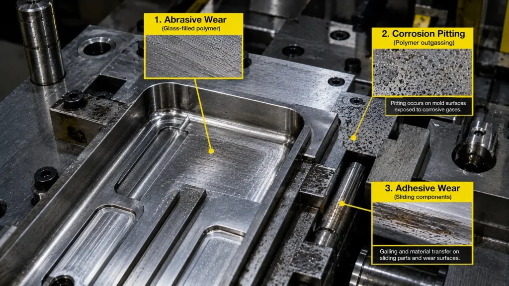
3.1 Abrasive and Erosive Wear
Abrasive wear is the dominant failure mode in molds processing reinforced engineering polymers. Glass fibers (typically 10–50% by weight), mineral fillers, carbon fiber, and flame retardants — all substantially harder than the H13 or P20 tool steel cavity surface — act as micro-cutting agents entrained in the polymer melt. At injection velocities of 50–200 mm/s, these particles impinge on cavity walls with persistent abrasive effect, removing substrate material cycle by cycle.
Erosive wear manifests most acutely at gate regions and directional changes in runner geometry, where the impingement angle of abrasive particles is highest and kinetic energy transfer to the cavity surface is maximized. Progressive dimensional loss at these locations distorts gate land geometry, alters melt flow dynamics, and eventually enables flash formation at parting lines. The downstream consequence is dimensional nonconformance across the entire part population — not cosmetic degradation confined to the gate area.
3.2 Corrosion from Polymer Outgassing
Certain engineering polymers release corrosive gaseous decomposition products during thermal processing. PVC generates hydrochloric acid; fluoropolymers release hydrofluoric acid; flame-retardant ABS and brominated HIPS emit hydrogen bromide. These acids attack unprotected steel surfaces with quiet persistence, pitting cavity walls and generating surface roughness anomalies that replicate onto molded part surfaces.
Corrosion is particularly insidious because it progresses invisibly between scheduled maintenance intervals. By the time cavity pitting is detectable through surface measurement, a population of nonconforming parts has already been produced. For such applications, corrosion-resistant surface treatment is not an optional performance upgrade — it is a production engineering prerequisite.
3.3 Adhesive Wear on Dynamic Components
Adhesive wear occurs when two metal surfaces in intimate sliding contact undergo micro-welding at asperity contact points. Upon separation, material transfers between surfaces and, in severe cases, substrate material pulls away with the transfer layer. Slides, lifters, side-actions, and guided ejector plates experience this mechanism continuously throughout service life.
Galling — the catastrophic macroscopic expression of severe adhesive wear — seizes sliding components mid-production, forcing immediate shutdown and emergency toolroom response. In high-volume production environments, unplanned downtime of even a few hours carries cost implications that dwarf the price of the preventive surface treatment that would have precluded the failure entirely.
4. Physical Vapor Deposition (PVD) Coatings
PVD coating technology is the most broadly adopted family of surface treatments in contemporary injection mold engineering. Technically mature, commercially accessible through a global network of job-coat suppliers, and available in a range of compositions suited to diverse application demands, PVD coatings deliver a compelling balance of hardness, friction reduction, chemical inertness, and dimensional precision unmatched by most competing processes.
4.1 How the Physical Vapor Deposition Coating Process Works
The physical vapor deposition coating process is conducted entirely within a high-vacuum environment, typically at pressures below 10⁻³ Pa. A solid target material — titanium, chromium, aluminum, or a multicomponent alloy — is vaporized through one of three primary mechanisms: cathodic arc evaporation, magnetron sputtering, or electron beam evaporation. In cathodic arc evaporation, a high-current electrical arc strikes the target surface, instantaneously vaporizing and ionizing target material. The resulting ionic flux is dense, energetic, and favorable for coating adhesion — though it carries the risk of generating macroparticles (molten target droplets) that must be managed through magnetic steering.
In magnetron sputtering, argon ions are accelerated into the target, ejecting atoms through momentum transfer in a gentler, more controllable process that produces smoother as-deposited surfaces — a meaningful advantage for optical or high-gloss mold applications.
Liberated target atoms traverse the vacuum chamber and condense on the mold substrate, building up a dense, adherent film of 2–8 µm thickness. A substrate bias voltage accelerates coating ions toward the mold, promoting atomic-level adhesion and ensuring low coating porosity. Process temperatures of 150–500°C are compatible with pre-hardened tool steels without risk of tempering softening — a prerequisite that immediately distinguishes PVD from thermal CVD.
4.2 TiN, TiAlN, CrN, and Beyond
Titanium nitride (TiN) — recognizable by its gold color — was the first PVD coating to achieve commercial scale and remains a cost-effective baseline for molds processing unfilled or lightly filled thermoplastics. Its hardness of approximately 2,300 HV and moderate oxidation resistance to 600°C remain adequate for low-to-moderate demand applications.
Titanium aluminum nitride (TiAlN) is the current workhorse of demanding mold environments. Its aluminum content enables formation of a protective alumina layer at elevated temperatures, pushing oxidation resistance to approximately 900°C and hardness to ~3,200 HV. For molds processing highly abrasive polymers or operating at elevated mold temperatures, TiAlN is the default specification in technically informed operations.
Chromium nitride (CrN) offers a distinct value proposition: moderate hardness (~1,800 HV) combined with superior corrosion resistance and lower compressive residual stress than titanium-based alternatives. Reduced internal stress permits thicker deposits on complex geometries — deep cavities, fine features, and blind recesses — without risk of delamination. CrN is the preferred specification for corrosive polymer environments and geometrically intricate tooling.
5. Diamond-Like Carbon (DLC): The Low-Friction Standard
Diamond-like carbon is not a compound of fixed composition but an amorphous carbon phase whose structure — and therefore properties — is continuously tunable through deposition parameters. The ratio of sp³ (tetrahedral diamond-like bonding) to sp² (trigonal graphitic bonding) governs hardness, friction coefficient, and chemical inertness. Deposition conditions that favor sp³ bonding produce harder, more diamond-like films; conditions favoring sp² bonding produce softer, more graphitic, lower-friction coatings.
As a low-friction coating for injection molds, DLC is unmatched among PVD-class treatments. Friction coefficients against steel in dry sliding range from 0.05 to 0.15 — an order of magnitude below uncoated tool steel on steel. This translates immediately into reduced demolding forces, cleaner part release, and the practical elimination of mold release agents in applications where contamination is inadmissible: medical device manufacturing, food-contact packaging, and optical component production are the canonical examples.
DLC also exhibits exceptional chemical inertness. It resists attack from acidic polymer outgassing products, aggressive mold cleaning solvents, and the surfactant-rich processing additives used with many engineering polymers. Hardness values range from 1,500 to over 4,000 HV depending on formulation. The primary constraint is thermal stability: standard hydrogenated DLC (a-C:H) graphitizes and loses performance above approximately 300°C. Silicon-doped DLC (Si-DLC) and tungsten-doped DLC (W-DLC) extend the thermal ceiling to 350–400°C and should be specified when sustained mold temperatures exceed 180–200°C.
6. Chemical Vapor Deposition (CVD) and PACVD
Chemical vapor deposition differs from PVD at its most fundamental level: coating material is delivered to the substrate as reactive gaseous precursors that decompose or react chemically at the mold surface, depositing a solid film in situ. The absence of line-of-sight geometric constraint is CVD’s defining advantage. Precursor gases diffuse into recesses, undercuts, blind holes, and internal features inaccessible to PVD — enabling truly uniform coating coverage on geometrically complex mold architectures.
This conformality advantage comes at a significant cost: process temperature. Thermal CVD requires substrate temperatures of 900–1,100°C, far exceeding the tempering threshold of virtually all injection mold tool steels. Post-deposition re-heat treatment is mandatory to restore substrate hardness — introducing dimensional change, adding lead time, and compounding costs. For precision tooling, this is frequently prohibitive.
Plasma-assisted CVD (PACVD) substantially resolves this limitation. By ionizing precursor gases with a plasma discharge, PACVD achieves deposition at 300–500°C — within the thermal tolerance of pre-hardened tool steels. Film density is somewhat lower than thermal CVD, but conformality is preserved. For molds combining complex internal geometry with tight dimensional tolerances, PACVD represents a technically sound compromise between the conformality of CVD and the temperature compatibility of PVD.
7. Electroless Nickel Plating
Electroless nickel plating is among the most established, accessible, and pragmatically useful surface treatments in the mold engineer’s repertoire. Its defining characteristic — autocatalytic deposition driven by chemical reduction without electrical current — produces coating thickness uniformity that electrolytic processes fundamentally cannot match. Since deposition rate depends solely on chemical activity rather than current density distribution, film thickness across the entire mold surface — including deep holes, narrow slots, and blind cavities — is essentially uniform.
The deposited nickel-phosphorus (Ni-P) alloy, with phosphorus content typically 6–12% by weight, exhibits as-deposited hardness of 450–600 HV. Post-deposition heat treatment at 300–400°C precipitates nickel phosphide (Ni₃P) particles, elevating hardness to approximately 900–1,000 HV. The elevated phosphorus content confers inherent corrosion resistance, making electroless nickel a practical, cost-accessible specification for molds processing mildly corrosive polymers.
Electroless nickel is rarely the optimal solution for severe abrasive environments — its hardness ceiling falls well below that of PVD nitride coatings. Its most defensible applications are moderate-wear corrosive environments, low-to-medium volume production molds where PVD economics cannot be justified, and as an intermediate adhesion-promotion layer beneath harder PVD topcoats.
8. Nitriding and Ion Implantation
Nitriding represents a philosophically distinct approach to mold surface hardening. Rather than depositing foreign material onto the substrate, it transforms the existing substrate chemistry through diffusion of nitrogen atoms into the steel matrix, where they react with chromium, vanadium, molybdenum, and aluminum alloying elements to precipitate hard nitride compounds in situ.
Plasma nitriding (ion nitriding) is the most controllable variant. Conducted at 100–1,000 Pa in a nitrogen-hydrogen atmosphere, a glow discharge plasma delivers nitrogen ions to the mold surface at controlled energy levels. Process temperatures of 450–550°C maintained for 4–48 hours produce case depths of 100–600 µm with surface hardness of 900–1,200 HV on H13 tool steel — without depositing any external coating layer.
The absence of a discrete coating-substrate interface is nitriding’s singular structural advantage. Delamination, spallation, and interfacial cracking — failure modes that afflict all coating-based treatments under high impact or cyclic loading — are simply not possible with a diffusion-hardened surface. The hardened zone grades continuously and metallurgically into the substrate. For molds subject to high mechanical impact or cyclic stress, this characteristic can be decisive.
Ion implantation takes the concept to its logical extreme: nitrogen, carbon, or boron ions accelerated to 50–200 keV bombard the mold surface at ambient temperature, modifying substrate chemistry to depths of 100–300 nm with absolute zero dimensional change. For ultra-precision molds where even sub-micron dimensional alteration from any thermal process is unacceptable, ion implantation is the only diffusion-based treatment that qualifies.
9. Advanced Surface Engineering Technology: The Next Generation
Advanced surface engineering technology is rapidly transcending the paradigm of single-layer, single-composition coatings deposited on passively prepared substrates. Multiple converging technological developments are reshaping what is achievable in mold surface performance.
Multilayer PVD nanolaminate architectures alternate coating compositions at the nanometer scale — TiAlN/TiN bilayer periods of 5–20 nm are representative. Layer interfaces deflect and arrest propagating microcracks through a crack-blunting mechanism, converting potential brittle fracture into contained microcracking. The resulting coating is simultaneously harder and tougher than any monolithic equivalent — a combination that conventional materials science teaches should be mutually exclusive.
Nanocomposite coatings disperse nanocrystalline hard phase particles — TiN, Si₃N₄, or TiAlN — within an amorphous matrix that inhibits dislocation motion and grain boundary sliding. Hardness values above 40 GPa are achievable in optimized formulations, with retained toughness that monolithic hard coatings at similar hardness levels cannot provide.
Laser surface engineering achieves surface modification without any deposited material. Laser surface melting resolidifies cavity surfaces at millisecond timescales, refining microstructure and increasing surface hardness through rapid solidification effects. Laser micro-texturing deliberately introduces controlled micro-dimple or micro-channel arrays that reduce effective contact area, trap lubricant, and substantially reduce friction in sliding components. Biomimetic structures — shark-skin drag-reduction patterns, lotus-effect hydrophobic arrays — are now directly manufacturable in mold cavity surfaces through precision laser ablation.
10. Industrial Coating Technology Comparison
An industrial coating technology comparison is most useful when structured around the specific performance requirements of the application rather than abstract technology rankings. The matrix below consolidates the essential differentiators:
| Technology | Hardness (HV) | Friction (µ) | Thickness (µm) | Max Temp (°C) | Conformality | Primary Application |
| TiN (PVD) | ~2,300 | 0.4–0.6 | 2–5 | 600 | Line-of-sight | Unfilled polymers |
| TiAlN (PVD) | ~3,200 | 0.4–0.6 | 2–6 | 900 | Line-of-sight | Abrasive filled polymers |
| CrN (PVD) | ~1,800 | 0.3–0.5 | 2–8 | 700 | Line-of-sight | Corrosive polymers |
| DLC | 1,500–4,000 | 0.05–0.15 | 1–4 | 250–400 | Line-of-sight | Medical, food, low-friction |
| PACVD | ~2,500 | 0.2–0.4 | 2–10 | 350 | Conformal | Complex geometries |
| Electroless Ni | 450–1,000 | 0.2–0.4 | 10–50 | 350 | Excellent | Moderate wear, economics |
| Plasma Nitriding | 900–1,200 | N/A | 100–600 | 550 | N/A | Impact resistance |
| Ion Implantation | 900–1,100 | N/A | 0.1–0.3 | Ambient | N/A | Zero-dimensional-change |
The practically optimal solution for many demanding applications is not a single technology but a combination strategy — plasma nitriding to build case depth and load-bearing capacity, followed by CrN or TiAlN PVD to provide surface hardness, low friction, and chemical protection. Understanding how technologies complement each other is as important as understanding each individually.
11. Surface Enhancement for Industrial Components: Transferable Knowledge
Surface enhancement for industrial components across cutting tool manufacturing, aerospace, automotive powertrain, and hydraulic systems has generated decades of rigorously validated performance data directly applicable to injection mold surface engineering. Cross-industry technology transfer is one of the fastest and most economical routes to mold performance improvement.
Cutting tool coating development has been the primary proving ground for TiAlN, nanocomposite, and multilayer PVD systems. The tribological demands at a cutting tool rake face — extreme contact pressures, temperatures above 800°C, severe abrasion at high sliding velocities — far exceed anything encountered in injection mold cavities. Coating systems qualified for cutting applications arrive at the mold problem with substantial performance headroom already validated.
Aerospace turbine blade thermal barrier coating (TBC) technology has advanced the fundamental science of designing coatings that manage steep thermal gradients while resisting oxidative and thermomechanical degradation. The temperature extremes of gas turbine environments exceed mold operating conditions by an order of magnitude, but the intellectual framework for thermal gradient management is directly applicable to mold cooling efficiency and resistance to thermal fatigue cracking.
Hydraulic component tribology — specifically, DLC performance under mixed and boundary lubrication conditions in hydraulic cylinders and piston rings — has generated a rigorous, quantitative understanding of DLC behavior across diverse contact conditions. This knowledge base directly informs the specification of DLC for mold sliding components and enables confident performance prediction without extensive application-specific testing.
12. Polishing, Texturing, and Pre-Coating Preparation
Surface engineering does not begin in the coating chamber. It begins on the polishing bench — and no coating technology, regardless of intrinsic performance, compensates for inadequate substrate surface preparation. A coating deposited over a poorly prepared surface faithfully replicates every defect in the substrate topology, and in some cases amplifies them through the coating’s own surface energy and roughness characteristics.
Optical-quality polishing for transparent polymer molds — PMMA, polycarbonate, optical-grade polystyrene — requires progressive diamond paste sequences from 6 µm through 1 µm, 0.25 µm, and to 0.1 µm or finer, achieving Ra values of 0.005–0.01 µm. This is painstaking, skilled craft work. Cross-contamination between abrasive grits — even a single coarser particle introduced during a fine-polishing stage — can create scratches that require restarting the sequence from an earlier grit. The investment in polishing skill and discipline is non-negotiable for optical mold applications.
Controlled mold texturing serves the inverse purpose: deliberately imposing topology to produce functional or aesthetic part surfaces without secondary operations. Photo-chemical etching imposes leather-grain, geometric, or wood-grain textures through resist masks. Laser micro-texturing offers superior design freedom and repeatability — enabling non-repeating pattern geometries, feature sizes below 10 µm, and biomimetic micro-structures impossible to achieve by chemical methods.
For context on how surface preparation integrates with broader process optimization strategies, improving plastic injection molding efficiency provides valuable perspective on the interconnected variables governing cycle time and part quality.
Pre-coating preparation within the coating facility is equally critical. The substrate surface must be free of EDM recast layers, machining-induced thermal damage, cutting fluid residues, and even fingerprint contamination. Pre-coating protocols typically include ultrasonic solvent cleaning, in-chamber plasma etching, and an argon ion etch cycle that removes native oxide and physically activates the substrate surface for maximum coating adhesion. Deviations from this protocol compromise adhesion in ways not immediately detectable — but that manifest as premature delamination after a fraction of the expected service life.
13. Choosing the Right Surface Engineering Partner
The surface treatment specification is only as effective as the supplier executing it, and selecting a surface engineering partner deserves the same systematic rigor applied to material procurement or capital equipment acquisition.
Technical process breadth is the first evaluative criterion. A supplier operating exclusively PVD equipment cannot objectively advise whether plasma nitriding plus PVD outperforms PVD alone for a given application — their recommendation will inevitably reflect available process capability rather than the mold’s actual needs. Seek suppliers with documented capability across multiple treatment technologies, or establish relationships with specialized suppliers for each process family.
Metrology and quality infrastructure is the second dimension. A credible partner maintains coating thickness measurement (calotest or ball crater method), micro-Vickers hardness testing, adhesion qualification (scratch testing or Rockwell indentation), and surface roughness measurement. Process certification data — not merely verbal assurance — should accompany every treated mold.
Specific experience with injection mold geometries matters and should not be inferred from general industrial coating competence. Injection molds present challenges — polished surfaces that must not be roughened, deep cavities, fine features, micron-level dimensional tolerances, and complex fixturing requirements — that are distinct from cutting tool or automotive component coating. Suppliers whose primary market is cutting tools may not have developed the handling protocols and process variants required for mold-quality outcomes.
Finally, technical communication capability is a practical proxy for overall capability level. A technically sophisticated surface engineering supplier engages meaningfully with failure analysis, proposes evidence-based process combinations, and provides performance data from comparable applications. A supplier that can only process an order cannot add the technical value that transforms a coating specification from a commodity purchase into an engineering decision.
14. Conclusion
The landscape of surface engineering solutions for plastic injection molds encompasses a rich, expanding, and technologically sophisticated array of treatments — each addressing specific failure mechanisms with distinct physical mechanisms, performance profiles, and economic characteristics. PVD coatings deliver hardness and wear resistance for abrasive polymer environments.
DLC provides unmatched friction reduction for clean-release and contamination-sensitive applications. CVD and PACVD offer conformality for geometrically complex tooling. Electroless nickel provides accessible corrosion protection at competitive cost. Nitriding and ion implantation modify the substrate itself, eliminating delamination risk at its source. Emerging multilayer nanolaminate architectures and laser surface technologies continue to expand the achievable performance envelope.
The engineer’s task is disciplined diagnosis — identifying the dominant failure mechanism, matching it to the treatment that addresses it most cost-effectively, accounting for substrate compatibility and dimensional implications, and selecting a partner with verified capability to execute the specification. Applied with precision, surface engineering solutions for plastic injection molds consistently deliver among the highest returns on investment available in injection molding operations — measured in extended tool life, reduced scrap, eliminated downtime, and sustained part quality across production volumes that unprotected tooling cannot reliably achieve.
FAQS
Service life depends on polymer type, filler content, injection parameters, and the specific PVD coating applied. On molds processing unfilled thermoplastics, TiAlN or CrN coatings routinely deliver 500,000 to over 1,000,000 cycles before measurable wear necessitates recoating. On molds processing 30–50% glass-filled nylon or PBT, service intervals typically range from 100,000 to 300,000 cycles. Recoating is feasible on most PVD-treated molds following controlled chemical stripping of the depleted layer and surface restoration.
PVD coatings are thin — typically 2–6 µm — and their dimensional impact is predictable and manageable. A 4 µm coating increases cavity wall dimensions by 4 µm per surface, reducing the corresponding part dimension by approximately 8 µm on a diameter. For tight-tolerance applications, cavities are machined with pre-compensation allowance accounting for the coating thickness. Experienced mold engineers and coating suppliers routinely manage this as a standard process step.
Yes. Recoating of service-worn molds is routine and economically attractive. The process requires stripping any residual coating from the previous cycle (typically through selective chemical or plasma stripping), restoring the substrate surface through polishing or minor metal removal, and recoating per the original specification — or an upgraded specification if the failure analysis indicates the original treatment was suboptimal.
PVC processing environments are among the most chemically aggressive encountered in injection molding. The combination of plasma nitriding for case depth and mechanical load support followed by CrN PVD for surface hardness and acid corrosion resistance is the most widely validated approach for this application. For lower-volume molds where PVD investment is difficult to justify, high-phosphorus electroless nickel (>10% P) provides adequate corrosion resistance at more accessible economics.
Standard hydrogenated DLC (a-C:H) is not recommended for molds operating continuously above 200°C, as graphitization degrades its hardness and tribological performance above this threshold. For elevated-temperature applications — hot runner systems, engineering resins requiring elevated mold temperatures — Si-DLC or W-DLC formulations extend thermal stability to 350–400°C. The specific mold operating temperature should always be confirmed with the coating supplier before specifying any DLC variant for high-temperature service.
Comments are closed